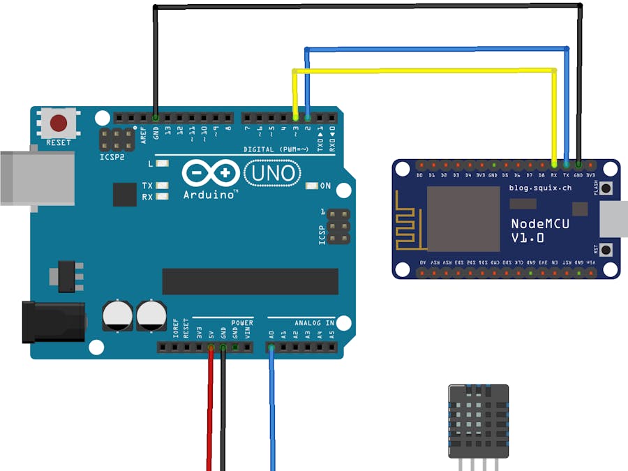
Komunikasi Serial Arduino
Komunikasi serial adalah komunikasi yang pengiriman datanya per-bit secara berurutan dan bergantian. Komunikasi ini mempunyai suatu kelebihan yaitu hanya membutuhkan satu jalur dan kabel yang sedikit dibandingkan dengan komunikasi paralel. Berikut adalah tutorial Lengkap cara membuat interface arduino dan visual basic melalui komunikasi serial. Di video ini teman-teman akan diajari secara komplit dari awal hingga visual basic dapat.
44 thoughts on “ Raspberry Pi and Arduino Connected Over Serial GPIO” • Siva Sankar Hello, I used the same wiring method and the data exchange is good. However it is not reliable, when i run a ping pong data exchange simultaneously for thousands and millions of time in a loop, and at the same time performing some motor controls from arduino (Motors are known to draw current up to 0.8 A), the data is getting corrupted.
The data corruption happens when the setup demands more current (for controlling motors). Measures taken by me to solve this problem, > Bow wow the price of fame itunes zip. i have added shield to the wires Tx and Rx. > grounding is verified properly. Still i dont know how when the setup draws more current, the data on Tx and Rx is corrupted. Any help will be appreciated. ↓ • roger Hello, I have a similar situation. I’d like to connect an Arduino Uno to a 3.3v sensor through RX/TX Now I understand Arduino-TX -> sensor-RX needs a voltage divider ( so the 5V of the arduino doesn’t break the sensor).
Now I’d expect the 3.3V from the sensor TX to Arduino-RX to be “safe”, however you mention in some situations the Arduino-RX can be at 5V, which would then go to the sensor and might break it So question ( assuming not using a level-divider) – why not have 2 voltage dividers? ( for both TX-RX and RX-TX connections) – could we put a schottky diode between the “Arduino-RX” to “sensor-TX”, to make sure there can only be a flow from the sensor to the Arduino, and and the diode blocks the other way around ( note: n00b here, so I might be completely misunderstanding it ). ↓ • Ralf S Hey Oscar! I just found your (super) instructions, and wanted to go through it. Funny, I already fail on the very beginning. On my Raspi3 the /etc/inittab file doesn’t exist. It seems it’s gone nowadays, see raspberrypi.org/forums/viewtopic.php?f=66&t=123081 But also when I follow the steps in the linked doc to deactivate getty, I don’t get your tutorial to work.
Hooking an oszilloscope to the Tx output of the raspi I don’t see anying coming there, so the minicom remains dead silent. Any hints on how to get this going with a new setup? Thanks, Ralf. ↓ • lcsbngg Hello, I have a question and i can not find the answer so maybe you can help me.
I have a raspberry pi with a python program (Tweet monitor learn.sparkfun.com/tutorials/raspberry-pi-twitter-monitor) When a tweet is found with the term i want it turn on a led (GPIO 22 HIGH) And i have a other program (a clock with 18 7-segment display) on a arduino mega, when a button is push (Pin 7 HIGH) the clock decrease one second. I wanted to know if it’s possible to plug the GPIO 22 (rpi) to the Pin 7 (arudino) and the GND to GND. I was afraid to kill the raspberry (because raspberry 3.3V and arduino 5V apparently) but in my situation it’s from the raspberry to arduino and only this way not the other. Thanks and sorry about my english.;). ↓ • RIVO I connect arduino Mega serial pins and raspberry type B GPIO with a adafruit voltage level converter I copied and pasted your code (python for Raspberry). Unfortunately when I type 103 in the arduino serial monitor, the raspbian terminal displays: character recieved: 1 character recieved: 0 character recieved: 3 and like that for all numbers (111, 100, 32 ).